The S0T-03-1G-C-**dBm downstream optical transmitter supports 870/1003/1218Mhz band and the DOCSIS 3.1 standard. The output optical power is from +6 dBm to +15 dBm available. It can be used for optical fiber transmission of downstream analog TV signals, digital television signals and CMTS data signals in HFC network. It has patented pre-distortion circuit, high CNR and low distortion.

Describe Product
Specifications
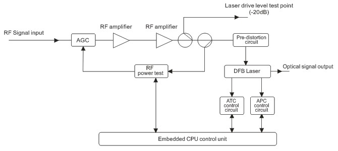
Schematic diagram
Specifications
|
Characteristics |
Unit |
Value/Performance |
|
Optical Parameters |
||
|
Laser Type |
- |
DFB Laser Module (OC-48 pinout compatible), with Isolator, with CNR = 51 dB min., CSO = 60 dB min., CTB = 65 dB min., with brand name from G7/EU countries |
|
Center Wavelength |
nm |
1310 ± 10 |
|
Connector |
- |
SC/APC (sleeve material: ceramic, connector with shutter) |
|
Output Power |
mW |
≥ 6.3 (8dBm) or ≥ 20 (13dBm) |
|
RF Parameters |
||
|
Input Level |
dBmV/ch |
15 to 25, or larger |
|
RF Amplifier Technology |
- |
1 * CATV GaAs or GaN Push-Pull and 1 * CATV GaAs or GaN Power-Doubler Hybrid Amp. Modules. All have brand name from G7/EU countries |
|
Gain Control Range |
dB |
0 ~ 10, or larger |
|
Input Impedance |
Ω |
75 |
|
Return Loss |
dB |
≥ 16 dB |
|
Bandwidth |
MHz |
82 to 1000, or larger |
|
Flatness |
dB |
≤ ± 0.75 |
|
Channel Loading |
- |
77 NTSC / 60 PAL channels + 320 MHz digital channels |
|
Link Performance |
||
|
(Test at temperature 25 degree C, 77 NTSC channels / 60 PAL channels Loading) |
- |
|
|
CNR |
dB |
≥ 52 @ link loss = 14dB ; ≥ 51 @ link loss = 15 dB |
|
CSO |
dB |
≤ -63 |
|
CTB |
dB |
≤ -65 |
|
Others |
||
|
Control Interface |
- |
RS232 / RS485 and RJ45. Support MIB table for SNMP Monitoring software |
|
Power Supply |
V |
100 to 240 VAC, 50/60 Hz, or larger |
|
Operating Temperature |
°C |
0 to 50, or larger |
Structure Description
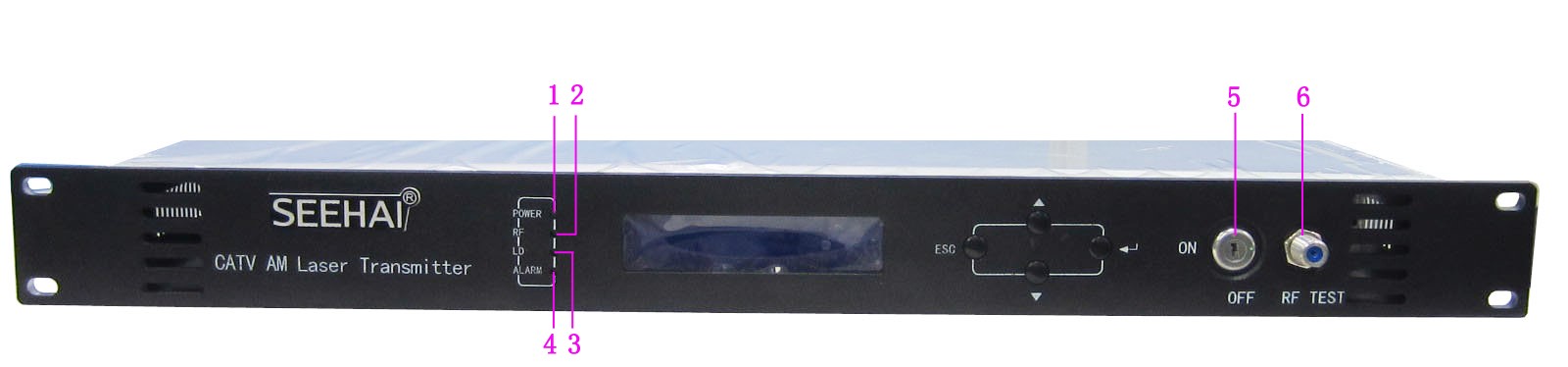
Front panel
|
1 |
Power indicator |
|
2 |
Laser drive level indicator: Steady green light: Drive level is normal. Blinking red light: Drive level alarm. You can view the alarm in the Alarm Status, the second level submenu. |
|
3 |
Laser working status indicator: Steady green light: The laser is operating normally. Steady red light: The laser is not turned on. Blinking red light: The device has a parameter alarm. You can view the alarm in the Alarm Status, the second level submenu. |
|
4 |
Device running indicator: This indicator will flash by 1Hz frequency after the device start running normally. |
|
5 |
Laser switch: ON: The laser is on. OFF: The laser is off. Keep the laser off before the device is powered on, and turn on the laser after the self-inspection is completed when power on. |
|
6 |
Laser drive level test port: -20dB |
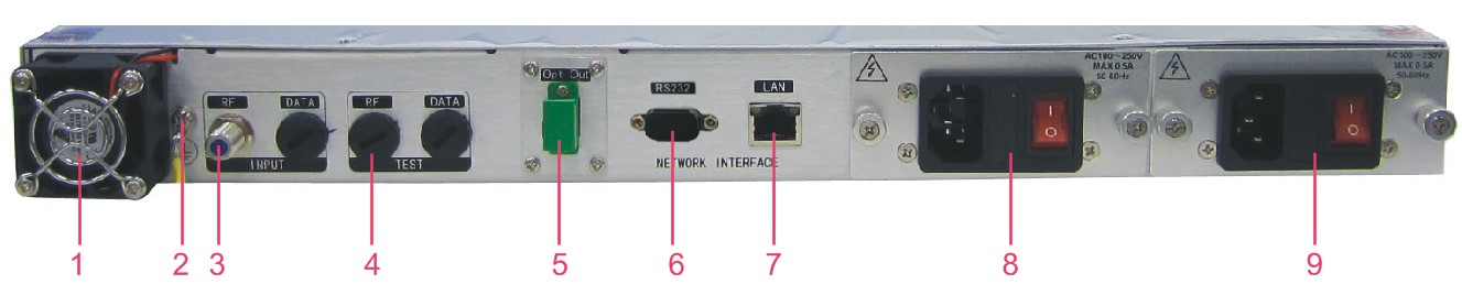
Rear panel
|
1 |
Fan |
6 |
RS232 interface |
|
2 |
Ground stud, ensure good grounding before power on |
7 |
LAN interface |
|
3 |
RF input 1 |
8 |
Power module 1, hot swappable |
|
4 |
RF input 1 test port -20dB |
9 |
Power module 2, hot swappable |
|
5 |
Optical signal output |
|
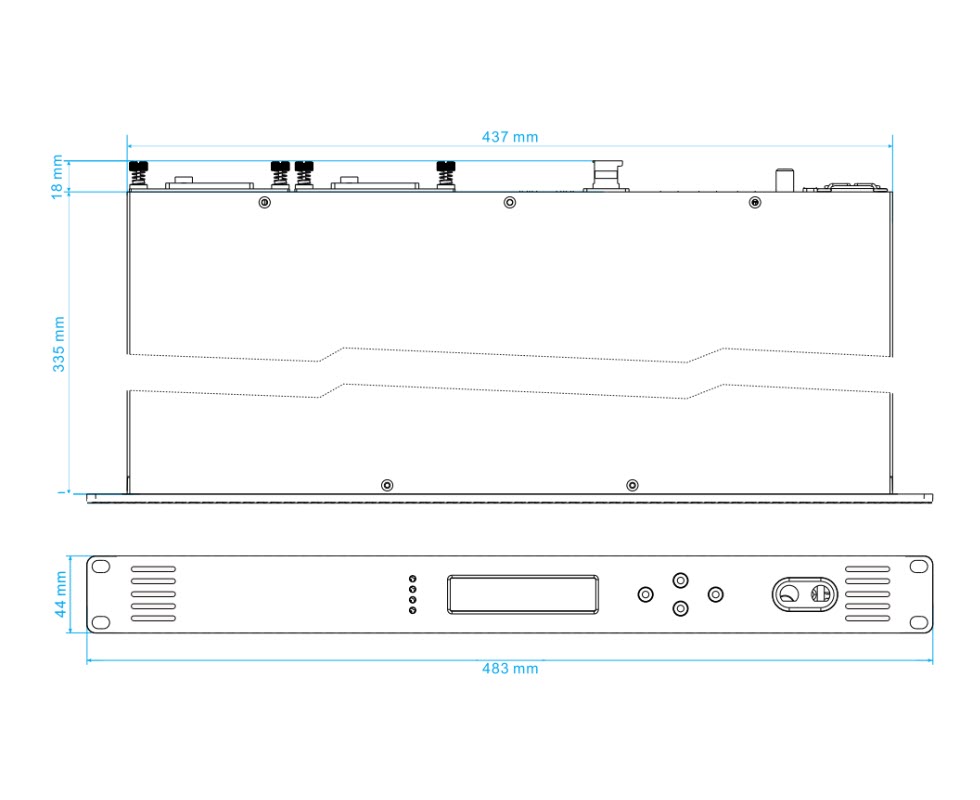
Dimension
Comment - Rating product